- 您现在的位置:买卖IC网 > Sheet目录320 > DEMO9S08AW60E (Freescale Semiconductor)DEMO BOARD FOR MC9S08AW60
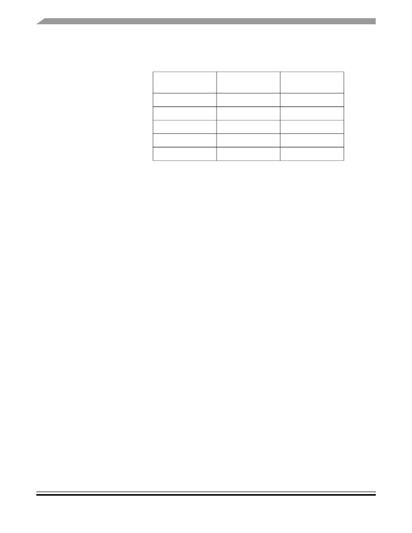
Table 1-11 Accelerometer (U5) Connections
Accelerometer
Function
Self Test
Amplified Y Output
Amplified X Output
Raw Y Output
Raw X Output
MCU Port
PTC4
PTD4
PTD5
PTD6
PTD7
J5
J6
J7
J8
J9
Jumper
1.13.5 Light Sensor
A photo detect IC (U4) combines a photodiode and a current amplifier on a
single IC to provide variable current. The light sensor is connected to the MCU
on PTD1. PTD1 can be disconnected from the light sensor by removing jumper
J4.
1.13.6 Potentiometer
A 10 Kohm thumb-wheel potentiometer (VR1) provides variable resistor for
users to assist them in application development. The potentiometer is connected
to the MCU on PTD0. PTD0 can be disconnected from the potentiometer by
removing jumper J3. The voltage seen on PTD0 is the result of a voltage divider
that changes as the potentiometer is turned.
1.13.7 I/O Connector
A 40-pin I/O connector (J35) is available for user expansion. This connector is
located on the bottom of the board and has holes so that pins of a connecting
DEMO9S08AW60E User’s Guide, Rev. 0.3
20
Freescale Semiconductor
发布紧急采购,3分钟左右您将得到回复。
相关PDF资料
DEMO9S08FL16
BOARD DEMO FOR FL16 FAMI
DEMO9S08JM16
BOARD DEMO FOR JM16 FAMI
DEMO9S08QD4
BOARD DEMO FOR MC9S08QD FAMILY
DEMO9S08QE8
BOARD DEMO FOR MC9S08Q
DEMO9S08SC4
DEMO BOARD FOR 9S08SC4
DEMO9S08SG32
BOARD DEMO FOR SG32/SH32 FAMILY
DEMO9S08SG8
BOARD DEMO FOR MC9S08SG FAM
DEMO9S08SV16
BOARD DEMO FOR SV16 FAMILY
相关代理商/技术参数
DEMO9S08DZ60
功能描述:开发板和工具包 - S08 / S12 9S08DZ60 DEMO BOARD RoHS:否 产品:Development Kits 工具用于评估:MC9S12G128 核心:S12 接口类型:CAN, LIN, RS-232, USB 工作电源电压:5 V 制造商:Freescale Semiconductor
DEMO9S08DZ60
制造商:Freescale Semiconductor 功能描述:9S08DZ60 DEMO BOARD
DEMO9S08EL32
功能描述:开发板和工具包 - S08 / S12 EL32 DEMO BOARD
RoHS:否 产品:Development Kits 工具用于评估:MC9S12G128 核心:S12 接口类型:CAN, LIN, RS-232, USB 工作电源电压:5 V 制造商:Freescale Semiconductor
DEMO9S08EL32
制造商:Freescale Semiconductor 功能描述:MC9S08EL Demonstration board
DEMO9S08EL32AUTO
功能描述:开发板和工具包 - S08 / S12 EL32 DEMO BOARD AUTO
RoHS:否 产品:Development Kits 工具用于评估:MC9S12G128 核心:S12 接口类型:CAN, LIN, RS-232, USB 工作电源电压:5 V 制造商:Freescale Semiconductor
DEMO9S08FL16
功能描述:开发板和工具包 - S08 / S12 DEMO BOARD FOR FL16 FAMILY RoHS:否 产品:Development Kits 工具用于评估:MC9S12G128 核心:S12 接口类型:CAN, LIN, RS-232, USB 工作电源电压:5 V 制造商:Freescale Semiconductor
DEMO9S08JM16
功能描述:开发板和工具包 - S08 / S12 DEMO BOARD FOR JM16 FAMI RoHS:否 产品:Development Kits 工具用于评估:MC9S12G128 核心:S12 接口类型:CAN, LIN, RS-232, USB 工作电源电压:5 V 制造商:Freescale Semiconductor
DEMO9S08JM16
制造商:Freescale Semiconductor 功能描述:; Development Tool Type:Hardwa
